CUSTOM PRODUCTS
Facilities
Offices and manufacturing space consists of all necessary departments to design and fabricate high tech products and prototypes. The machine shop is well equipped with appropriate machinery to support a high tech electronics company. In addition to standard electronics test equipment, an IBM computer is the central processing unit for the company’s microprocessor software development system.
Personnel
Technical employees available to the special projects team include:
| Electronic Engineers | Mechanical Engineers |
| Electronic Technicians | Mechanical Designers |
| Prototype Machinists | Prototype Wiremen/Assemblers |
| Technical Writer (Engineer) | QA Personnel |
TYPICAL SPECIAL PROJECTS
DESIGN AND FABRICATION
TO
CUSTOMER REQUIREMENTS
Description
- Depth/Altitude Sonar Digitizer for NR-1, naval research submarine. Under contract from Sperry, Great Neck, NY – for US Navy.
- Barge Draft Profiler upward looking multiple transducer sonar system (hardware and software). Under contract from US Army Cold Regions Research Engineering Labs.
- Multiple Transducer Sonar System for “swath” profiling of near shore sea floor; hardware and software; for small boats. US Army Corps of Engineers and Great Lakes Dredge and Dock Co.
- Cylindrical Pressure Housings for towed vehicle electronics. Under contract from the Naval Research Laboratory.
- Computer controllable 18kHz 2 KW transceiver for Naval Air Development Center for use on US Navy deep ocean swath bathymetry boats.
Personal Watercraft Surveying System (PWSS)
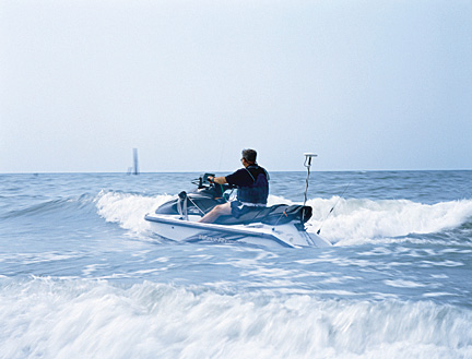
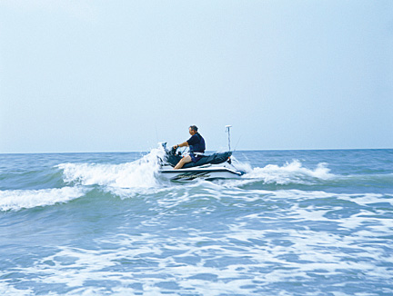
Personal Watercraft Surveying System (PWSS) is designed as a highly mobile, hydrographic surveying vessel especially useful in shallow water areas: surf zone, coral reefs, berths and docking areas, ponds, canals, marinas, remote areas, aquatic animal habitats and military applications. (Let us know your applications). The PWSS is operated by one person. Once the PWSS equipment is turned on and initiated, the system is automatic and survey management is in the hands of the shore based, survey control manager.
Safety is by no means a minor concern and, we believe, that the personal watercraft is quite safe because of maximum operator visibility, excellent maneuverability and the fact that the operator is on, not in, the craft and could get off easily, if necessary. The PWSS operator has only to steer the craft and does not have to operate any electronic devices, so no potential distractions are introduced.
PWSS has a draft of only a few inches and because the craft has a jet drive, there is no prop to get damaged from hitting underwater obstacles.
Ease of transport and deployment are also significant advantages over a full size survey boat.
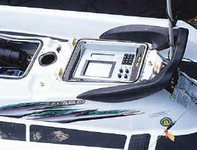
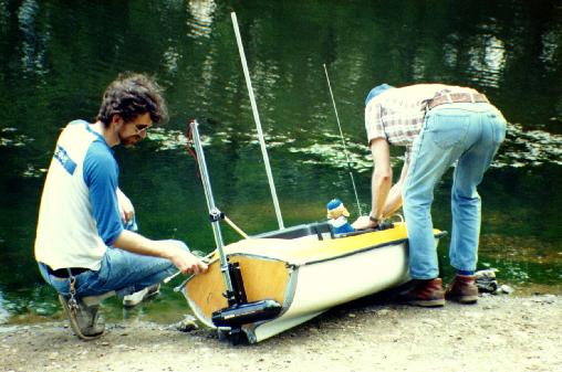
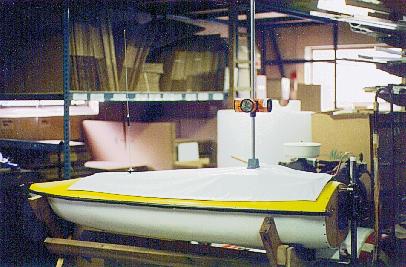
The PWSS photographs show an 85 HP jet drive Yamaha Wave Runner which has adequate front and rear compartment storage space for the electronics. Many other makes and models may be suitable, call our sales department for further advise in this regard.
APPLICATION DEPICTED IN PHOTOS
Owner/operator of PWSS: Brunswick Surveying, Supply, NC.
Brunswick’s ongoing project using PWSS is located in Bald Head Island, NC. The project consists of a multi-year contract to repeat 30 survey lines from the beach to approximately 3000 feet offshore. The objective of the survey is to monitor the erosion of the beach, determine where the sand is going, where additional sand is coming from, what factors are contributing to the erosion and what measures can be implemented to help control the erosion.
The magnitude of the tide fluctuation and the size of the expanded project posed some unique problems. Brunswick wanted to over lap the wading survey with the hydrographic survey and wanted to work at any stage of the tide. Since it is dangerous to operate a full size survey boat too near the surf zone they would be limited to a 3 hour working windows (at high tide) with a full size survey boat. In addition, the wading survey would have to then be done at low tide to get an appropriate survey line overlap. Of course, high tide falls in mid-day one week and low tide falls in mid-day the next week further complicating the situation. On top of this, they needed relatively calm weather and sea conditions. It became obvious, that a system must be devised to enable Brunswick to work on any day with appropriate weather and sea conditions.
The Personal Watercraft Surveying System (PWSS) was developed to fulfill the requirements of the project described above.
EQUIPMENT
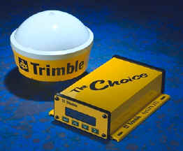
The equipment selected includes and Innerspace 455 Survey Depth Sounder, Innerspace 453A RF modems, Innerspace 603 Remote Indicator and Innerspace Datalog with Guidance Software (DLWG). The GPS used in Brunswick’s PWSS is an Ashtech GG24 RTK system, which was owned by Brunswick prior to acquiring the personal watercraft. Future PWSS systems will utilize Trimble GPS. Position accuracy can be either sub-meter DGPS or a few centimeters RTK. Depth resolution is .1 foot or .01 meter as selected by the operator. The GPS can be a Trimble MS750 for RTK or an AgGPS 132 or similar unit for DGPS. A special multiplexer was developed, the Innerspace 905, to synchronize the depth and RTK position data at 1PPS available in the GPS receiver. A bi-directional voice radio system is also included. The balance of the equipment includes: system batteries for power & associated charger and wiring junction box. All the equipment is mounted out-of-sight, in closed compartments, except for the 603 which provides guidance for the operator and the GPS and RF antennas and depth sounder transducer. The instrumentation is all mounted with quick release mechanisms to facilitate easy removal so the equipment may be used on projects where the personal watercraft is not applicable.
ON PERSONAL WATERCRAFT
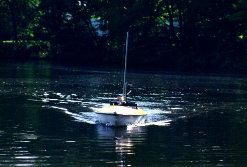
On Watercraft: The equipment installed in the personal watercraft consists of an Innerspace 455 Survey Depth sounder mounted under the rear seat, one Innerspace bi-directional RF (UHF) modem, and Ashtech GG24RTKGPS, an Innerspace 905 Multiplexer and a bi-directional voice radio VHF all mounted in the front compartment. An Innerspace 603 Remote Indicator is mounted above the steering bars in full view of the operator. The GPS antennas and three separate RF systems antennas are strategically located about the craft and the depth sounder “kickup” transducer is transom mounted. The watercraft’s electronics systems are powered from a separate battery/charger installation located under the 455 sounder in the rear compartment. The watercraft’s engine/starter power system is not used for the electronics except to power the battery charger that charges the separate battery that powers the electronic systems. In some applications a heave, pitch and roll compensation device may apply to remove much of these motion components, however, a heave compensator also adds substantially to the cost of PWSS.
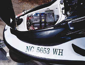
FRONT COMPARTMENT
REAR COMPARTMENT
ON SHORE
On Shore: The shore based equipment consists of Innerspace Datalog With Guidance Software installed on a single port notebook computer, the RTK reference station, one half of the Innerspace bi-directional hydrographic UHF data link, the transmitter half of the RTK UHF data link and one half of the bi-directional voice radio VHF link. For some applications sub-meter DGPS may be adequate position accuracy. Advantages of using DGPS over RTK is ease of use and relatively low cost. A disadvantage of DGPS is the inherent inaccuracy in the elevation making the elevation component unusable.
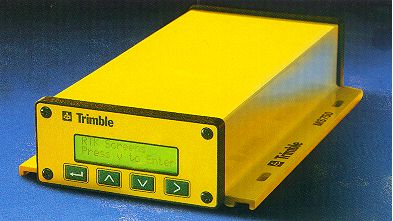
AgGPS132
SUBMETER DGPS, LOW COST
MS750 MARINE GPS
RTK CENTIMETER ACCURACY
OPERATION
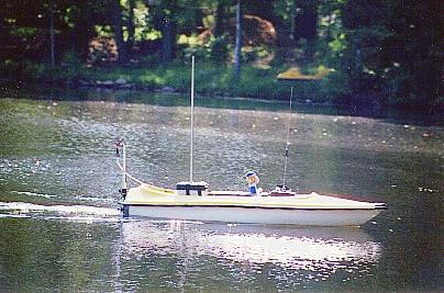
Operation: The Personal Watercraft (PWSS) is operated by one person who simply has to control the speed of the craft and left/right steering as indicated by the easy-to-read, Innerspace 603 display. There are no electronic systems to adjust while underway – everything is automatic. Via the 603 display, the operator has an analog left/right steering indication and actual distance off line. Distance to start of line, bearing to start of line, distance to end of line and depth are also displayed. It should be noted that the 455 Depth Sounder, because of its state-of-the-art design, is both small and lightweight allowing it to fit inside PWSS. It not only provides digitized depth for the data collection software, but it also has an analog mission storage feature allowing the LCD chart screens to be stored on a single chip FlashDisk. Then, if anomalies in the digitized data are noticed, the analog charts can be recalled for closer examination of the area in question.
Data collection is via Innerspace’s Datalog With Guidance Software (DLWG) and is located in a shore based computer. The bi-directional Innerspace 453A RF modem system is the data link that receives depth (in Innerspace format) and position data (in NMEA format) from PWSS and sends pertinent information to the Innerspace 603 LCD helmsman display on PWSS. This information, including trackline guidance, is displayed on both the shore based computer and the 603 display on PWSS, simultaneously. RTK corrections, are sent to PWSS via the RTK GPS modem. To ensure depth/position accuracy, depth is time tagged to 1PPS furnished by the GPS system. The third RF communications system is a voice link to enable shore station personnel to communicate to the PWSS operator.
DATA PROCESSING
The hydrographic data collected in Datalog With Guidance Software is converted into an X, Y, Z comma delimited file for Autocad Land Development or other similar terrain modeling processing software such as Surfer or Grapher. A digital terrain model is generated from the coordinate files and cross section and topographic maps are generated from the terrain model.
According to Mr. Tom Morgan, owner of Brunswick Surveying, Brunswick Surveying is pleased with the performance of the PWSS because it has enabled them to plan their survey day without consideration of the prevailing tide stages. This provides for tighter control of costs and enables a reasonable estimate of when a particular series of survey lines can be completed.
Safety, is by no means a minor concern and, we believe, that the personal watercraft is quite safe because of maximum operator visibility, excellent maneuverability and the fact that the operator is on, not in, the craft and could get off easily, if necessary.
Ease of transport and deployment are also significant advantages over a full size survey boat. Finally, the PWSS operator has only to steer the craft and does not have to operate any electronic devices, so no potential distractions are introduced.
Once the PWSS equipment is turned on and initiated, the system is automatic and survey management is in the hands of the shore based, survey control manager.
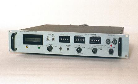
MODEL 451 DEPTH SOUNDER SIMULATOR
The 451 Depth Sounder Simulator is a depth sounder service instrument. It allows a depth sounder to be tested on shore under simulated “at sea” conditions.
The 451 accepts a transmitted pulse from a depth sounder, delays it and transmits it back to the sounder over the same line. The simulator output pulse, simulating a bottom return, is variable in amplitude by a front panel control. So, the receive sensitivity of the sounder can be determined for any selected depth entered from the 451 front panel.
Frequency of the depth sounder being tested can be entered via the 451 front panel thumbwheels. Sonar pulse width and sound velocity in water are also front panel entries.
The 451 was originally built for a military ship program and since commercialized and sold to non-military customers as well.
For further details; contact our sales department
REMOTE CONTROLLED HYDROGRAPHIC SURVEY BOAT
For performing specialty hydrographic surveys. Ideally suited for very shallow water, contaminated environments other hazardous areas. System includes: depth sounder, positioning (either Total Station or DGPS), RF telemetry for X-Y-Z data, RF Telemetry for remote joystick control and electric trolling motor. Data collection computer is on shore.
Specifications
| Draft | 9″ | Length | 6′ 7″ |
| Beam | 30″ | Hull | 3/16″ polyethylene |
| Range | 1000 meters | Speed | variable to 4 knots |
| Weight | 155 lbs. complete (50 lbs. boat and motor) | Endurance | 3 – 4 hours |
Tethered Sounding System (TSS)
The TSS is manually pulled across a stream, creek or river taking digital depth soundings and transmitting them to shore via RF modem.
Applications: To produce cross sections for purposes of bridge scour monitoring or other DOT related projects in areas where survey boats cannot be used. The system also has application near dams and in shallow ponds (natural or man made).
Equipment in Waterproof Box: Innerspace Model 445 Autotrack digital echo sounder digitizer, Innerspace Model 453A UHF data link for transmitting depths to shore, battery for internal power and prism pole with 6 prism array.
Equipment On Shore: Total station manual or auto-tracking with RS232 output, Model 453A UHF data link for receiving depths from TSS, computer with Innerspace Datalog With Guidance software installed for data collection of depths and range azimuth in ASCII format.
TURBIDITY MONITORING SYSTEM (TMS)
General:
Innerspace has developed and offers a turnkey turbidity monitoring system (TMS) for the dredging of contaminated sediments such as PCB’s, or any project where down river/ down current migration of bottom sediments is undesirable.
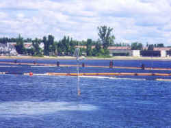
The initial installation was in Lake Champlain for PCB dredging by Sevenson Environmental Services. With contaminated sediments, it is important that the bottom material is not stirred up, put into suspension and allowed to migrate out of the immediate dredge area. The Innerspace TMS monitors a number of turbidity sensors mounted on the dredge and moored in the surrounding area. A central computer onshore interrogates the remote turbidity stations one at a time, automatically, at a pre-selected rate. The received data, turbidity and battery condition, are displayed on screen and logged to a disk file on a continuous basis. An alarm is displayed, logged and sounded if predetermined turbidity levels are exceeded.
While the number of turbidity stations might vary from project to project, a typical deployed system consists of five strategically placed turbidity meters with solar panels, Innerspace 453A coded RF modem with 8 bit micro controller/digitizer, battery charger controller, cables and complete mounting hardware.
The shore station consists a of an Innerspace 453A RF Modem, laptop Pentium computer, Innerspace TMS software and system cables.
With installation and training provided by Innerspace, the system is truly a turnkey environmental dredge monitoring system.
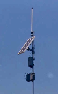
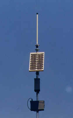
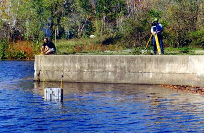
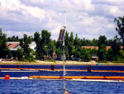
TURBIDITY MEASURING STATION
Consisting of: RF Antenna, Solar Panel, 453A RF Modem, Battery/Charger Assembly, Mounting Pole and Turbidity Sensor (not shown)
Description
Consisting of: Solar Cell, Rechargeable Battery, Coded RF Modem with 8 bit micro controller/digitizer, RF Antenna, Turbidity Sensor and Pole Assembly (Buoy Mount Optional)
The turbidity sensor uses infrared technology and measures in Nephelometric Turbidity Units (NTU). In the pole mounted configuration (shown in photo) the turbidity sensor is protected inside the adjustable section of aluminum pipe. A cut out in the pipe allows the sensor access to the water.
Each station is a complete assembly and any number of stations can be used on a job site. Each RF modem (radio link) is coded so each station in an array can be interrogated, monitored and identified remotely from shore by its own unique code. The station is designed to operate on a 24 hour basis with very low maintenance requirements.
Turbidity Station – insitu
TMS DREDGE GRAPHICS SUB-SYSTEM
General
While TMS can be used for any turbidity monitoring application, it is most applicable to dredging projects because of its real-time operation and display during ongoing dredging. For applications other than dredging, a simpler turbidity storage device could be used whereby the data is collected over time and retrieved or downloaded at any convenient time. Real-time access to the data would usually not be required for non-dredging applications.
Description
When using TMS for dredging applications, a separate dredge graphics system is available to provide precise position and attitude of the dredge and to graphically display digging operations along with turbidity in real-time. This system consists of two Trimble AgGPS 132 sub-meter GPS receivers, DC power supply, Pentium computer, Windows operating system, SVGA monitor, dredge graphics software, turbidity sensors and mounting hardware.
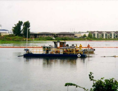
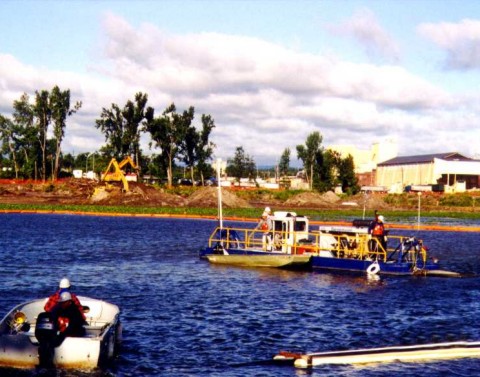
Sevenson Environmental Dredges on site – Lake Champlain
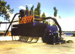
Components of Hazardous Waste Processing Plant
Operated by Sevenson Environmental
Lake Champlain Area – New York State